
Problem statement — why prototypes stall before production
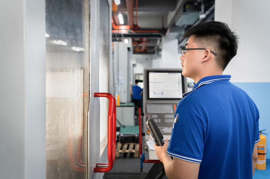
Engineers frequently hand a successful prototype to manufacturing and watch lead times and scrap rates spike; the root problems are usually geometric complexity, inadequate machine strategy, or fixturing that fails under load. When a component requires continuous 5-axis tool access, a simple CAM-to-machine handoff often breaks: wrong toolpaths, collision risks, and coordinate misalignments add hidden hours. Teams that incorporate controlled trials with dedicated 5 axis cnc machining services early avoid those failures by validating actual kinematic behavior against the digital model.
Root causes — technical failures you can measure
Tolerance stack-ups become obvious once you remove the assumption that a “prototype” equals a finished process. Common, quantifiable failures are: (1) fixture deflection beyond allowable microns under cutting forces; (2) thermal growth on long-cycle pockets causing surface deviation; (3) tool deflection when cutting titanium or high-strength steels with long overhangs; (4) post-process coordinate drift after multiple setups. Each issue maps to a measurable parameter: strain on fixture, temperature delta across the part, tool deflection values (F/EI), and repeatability of machine encoders. Addressing these requires instrumentation and targeted corrective actions, not vague process improvements.
Verification methods — how to confirm a prototype is producible
Start with dimensional control: use CMM routines that replicate production clamp orientations, and capture datums in the same sequence the shop will. Add in-process probing to detect cumulative errors between setups; log readings to establish whether errors are systematic or random. Surface integrity needs microscopic review for burrs and sub-surface cracks after high-feed titanium cuts. Monitor tool wear through measurable runout and flank wear thresholds; replace tools on condition rather than arbitrary time. These steps turn subjective “looks good” assessments into reproducible go/no-go criteria.
Real-world anchor and practical manufacturer integration
Lessons from large manufacturing showcases such as Hannover Messe reinforce a clear pattern: teams that pair design intent with shop-floor metrics reduce first-pass failure. Field validation often happens through partnerships with specialist suppliers; engaging a reputable 5 axis machining manufacturer lets you reconcile CAM simulations with actual machine kinematics, fixture behavior, and cycle-time data before scaling. That external check supplies empirical runs that reveal whether a design needs geometry simplification, changed material temper, or an alternate machining sequence.
Process remedies — concrete steps to move to production
Implement these fixes in order: (1) lock down datums and design for modular fixturing so single-setup machining is possible; (2) reduce tool overhangs and optimize toolpaths for constant engagement to limit chatter; (3) select tool grades and coatings matched to material and cycle length; (4) codify probing routines into the NC program to catch offsets early; (5) run a 1:1 pilot on the intended machine to collect actual cycle times and thermal behavior. Each action links to clear acceptance criteria: maximum deflection, surface roughness Ra, and cycle-time variance thresholds. Prioritizing these fixes shortens qualification time and lowers scrap ratios.
Alternatives and trade-offs — when 5-axis is not the optimal choice
Full 5-axis machining gives access and reduces setups but increases CAM complexity and collision risk. If the geometry allows, 3+2 indexing can cut programming time and simplify fixturing at the expense of some tool access. For thin-walled or highly stressed sections, consider hybrid approaches: near-net additive for the complex core followed by subtractive finishing to meet tolerances; EDM for internal features that are inaccessible even with 5-axis. Evaluate each option by measuring total cost of ownership: cycle time, fixture cost, tolerance yield, and inspection burden.
Common pitfalls — avoid these mistakes
Do not accept a “close enough” prototype without metric thresholds. Avoid overcomplicating the CAM strategy to chase marginal cycle-time gains; complexity multiplies failure modes. Don’t ignore the machine’s kinematic limits—high-speed options reduce cycle time but amplify thermal and dynamic errors if control parameters aren’t tuned. Lastly, failing to record and iterate on real run data prevents continuous improvement; a documented feedback loop from shop floor to design is mandatory.
Conclusion — a concise, technical decision path
Make the decision sequence objective: verify with a pilot on a target machine, measure against predefined tolerances, and adjust design or process based on instrumented data. When continuous tool access and complex contours matter, validated 5-axis runs eliminate guesswork and expose hidden constraints. Practical collaboration with experienced manufacturers converts prototype geometry into production reality, and that is precisely the role Hanstar fulfills by aligning simulation, machine behavior, and measurable acceptance criteria so parts move from concept to reliable production.