
Intro: A Quick Stop That Isn’t So Quick
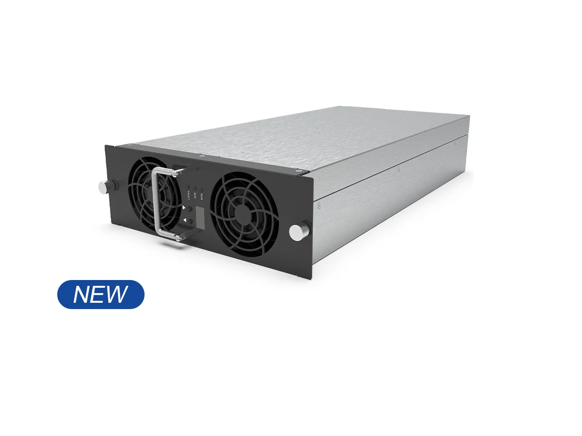
You roll up to a busy station on a rainy night, hoping for a fast top‑up and a warm drive home. Behind it sits the power module for EV charger that either keeps you moving or makes you wait. Now picture this: most drivers expect 80% charge in about 20–30 minutes, yet a few minutes lost to conversion loss or thermal throttling can feel like forever (especially when the line grows). So here’s the crunch—if the module’s guts aren’t efficient and stable, the “fast” in fast charging can dissolve. Why do some sites feel snappy while others lag?
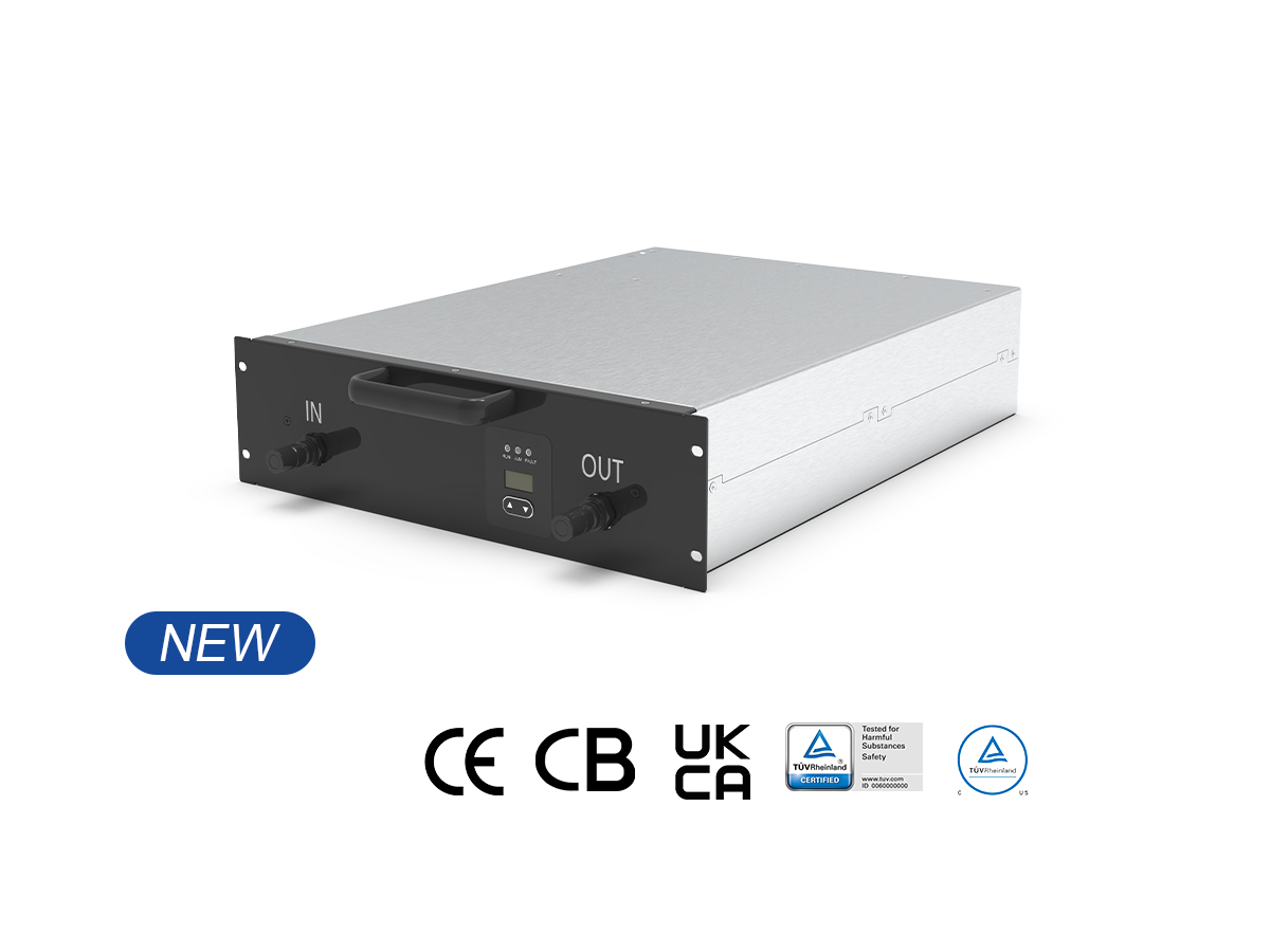
That answer hides in the stack: rectification, isolation, and DC‑DC stages. Each part adds heat, noise, and delay. Miss the thermal window, and the system pulls back power to protect itself. Skimp on control loops, and the output hunts. The result is a stop that takes longer than it should—funny how that works, right? Let’s look under the hood and unpack the real bottlenecks before we compare what’s next.
Why Old Designs Stall: The Quiet Flaws People Don’t See
What’s actually slowing you down?
Let’s go technical and keep it plain. Many legacy units lean on hard‑switched topologies with slow switching devices. That means more heat, more losses, and less usable current when you need it. When ambient temps rise, thermal headroom shrinks. The system then derates to stay safe—so your car charges slower. Look, it’s simpler than you think: poor thermal management plus high switching loss equals time wasted. Add in clunky control with coarse sampling and you get sluggish response to load steps.
Another issue: weak galvanic isolation or aging isolation transformers can raise noise and stress components downstream. That feeds into EMI problems, which forces conservative settings on the control loop. In many sites, you’ll also find limited CAN bus telemetry. Without clean data, operators can’t tune modules in real time. The result is a chain reaction—more ripple, more heat, more derating. Meanwhile, silicon that isn’t optimized (say, older silicon IGBTs) struggles at higher duty cycles compared with modern SiC MOSFETs. And when the PFC stage is just average, grid harmonics go up, efficiency goes down, and the whole cabinet feels “sticky.” You see only the wait; the module feels the math— and yes, it matters.
From Fixes to Future: How New Principles Change the Stop
What’s Next
New designs are shifting to soft‑switching DC‑DC stages and high‑frequency transformers to slash switching loss. Add wide‑bandgap devices like SiC MOSFETs, and you get lower conduction loss at higher voltage and current. That means less heat, steadier power, and tighter control loops. In plain terms: more usable kW to the car, more of the time. Advanced thermal paths—vapor chambers, smart cold plates, better TIM—keep junction temps in a sweet zone, so the module won’t pull back power when the site gets busy. And with higher‑resolution sensing plus fast digital control, the output doesn’t “hunt” when the EV’s battery management system demands a sudden change.
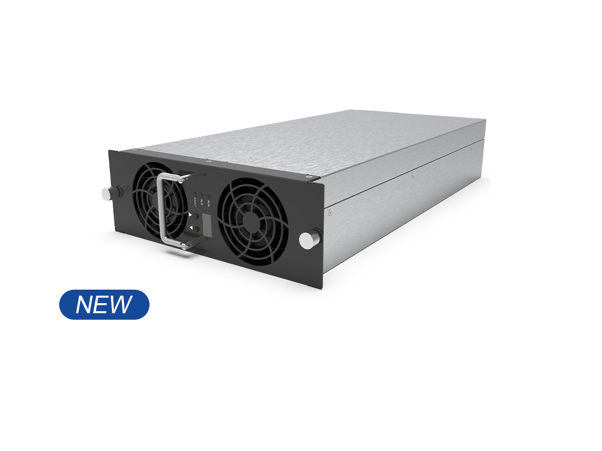
On the grid side, improved power factor correction and cleaner EMI filter design reduce stress on upstream breakers. That supports denser sites without drama. When you see a DC fast charging power module run cool and quiet, you’re also seeing good topology choices—interleaving, robust isolation, and responsive firmware. Together they unlock faster sessions and fewer surprises. It’s not hype; it’s engineering that trims seconds at each stage, which adds up across a queue.
Head‑to‑Head: What Better Looks Like in Practice
Let’s compare outcomes you can feel. With modern soft‑switching and SiC, efficiency in the DC‑DC stage jumps several points versus older hard‑switched designs. That sounds small, but it’s the difference between the module staying in its thermal comfort zone or crossing a limit and derating. Better control bandwidth also shrinks the time to settle after a big load step from the EV—so the current you see on the screen reaches target faster.
There’s also resilience. Improved isolation and smarter firmware mean fewer nuisance trips and tighter protection thresholds. Sites with clean CAN bus telemetry can watch thermal gradients in real time and balance load across cabinets. That leads to more stable queues and fewer “why is this one slow?” moments. Put simply: fewer stalls, more consistent power, and happier drivers. The lesson: optimization isn’t one thing—it’s a system stack tuned to move watts without waste.
How to Choose: Three Metrics That Keep You Moving
Advisory, quick and clear. If you’re comparing modules, use these three checks before you buy or spec:
1) End‑to‑end efficiency at realistic load. Not just peak. Ask for a curve from 20%–100% load, with ambient temp stated. A solid design holds high efficiency across the band. Include the PFC and DC‑DC numbers so you see the whole path.
2) Thermal behavior under stress. Look for continuous output at elevated ambient (e.g., 40–50°C) without derating for a defined time window. Check the cooling method and the actual junction temperature margin. Reliable thermal management beats big marketing claims—funny how that works, right?
3) Control and data visibility. You want fast transient response (milliseconds), stable current ripple, and clean telemetry via CAN or Ethernet. If operators can’t see it, they can’t fix it. And if the loop isn’t stable, the car won’t get steady power.
Use these to filter noise from signal. They’ll point you toward designs that cut wait time, protect the grid, and scale well as sites grow. For a grounded benchmark and more technical detail, keep an eye on brands building with these principles, like winline charger.