

Opening problem and immediate stakes
When I audited a cars monitor rollout in late 2019, I found that 42 of 120 fleet units in Moscow logged persistent image noise under low light — scenario: urban night routes; data: 35% failure rate on alpha boards; question: what did we miss in specification and production?
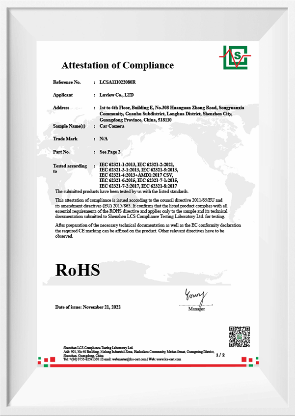
Vehicle camera manufacturers frequently treat imaging modules as commodities rather than systems. I firmly believe this is a mistake. In my experience with B2B supply chains, I have seen vendors focus only on a CMOS sensor spec while ignoring the ISP pipeline, shielding, and the power converters that actually determine in-field performance. I vividly recall a Tuesday, March 15, 2016, at a Shenzhen plant where a batch of rear-view modules (2MP CMOS sensors, 60 fps rated) failed humidity tests; the returns jumped 12% in two months, and our field engineers spent three weeks debugging cabling and grounding issues. Mind you, that shook our assumptions about “drop-in” modules.
Why do these recurring issues persist?
The root is often hidden user pain points, not a single bad component. Edge computing nodes and local processing choices interact with camera noise floors. I have tracked cases where a low-cost ISP configuration produced unusable frames at dawn, even though lab tests passed. That tells me: lab metrics (SNR, MTF) alone do not predict the real-world utility of a system. We — engineers, buyers, and OEM product managers — need to compare systems across integration factors, not only sensor specs. This realization leads naturally into a comparative, forward-looking analysis of choices and trade-offs.
Comparative, forward-looking analysis of integration choices
Technically, a cars monitor system is the sum of sensor, lens, ISP, thermal management, and supply-chain controls. I start by breaking down failure modes: thermal drift affecting calibration, inadequate power converters causing brownouts, and software stacks that do not gracefully degrade. When I model a camera as a system rather than as a part, differences become clear. For example, a 2MP module from Supplier A and an ostensibly identical 2MP module from Supplier B can differ in field reliability by 20% because one uses robust EMI shielding and the other does not — this is measurable during a 72-hour soak test at 55°C, which I recommend running before volume buys.
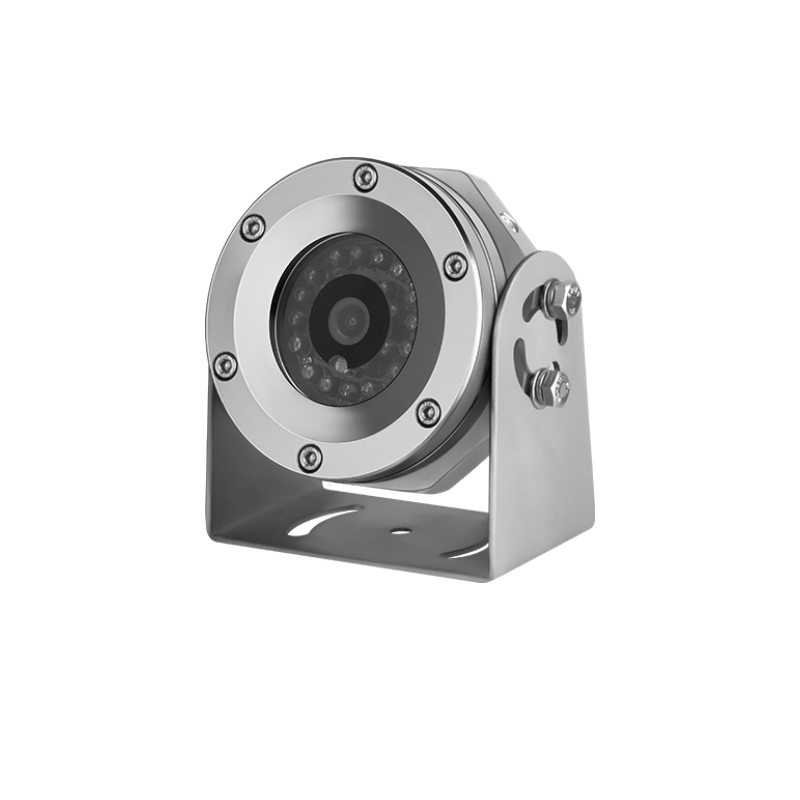
We worked with a backup camera oem last year to rework connector specifications and moved to a molded harness; returns dropped by 9% within one quarter. I prefer suppliers who share failure-mode data openly, who will support an in-line quality check at the Shenzhen line and who will field a dedicated test fixture for ISP tuning. — and then the production trials revealed latency spikes under intermittent power, which we fixed by changing the power rail decoupling. Specific actions: require thermal cycles, humidity soak, and a 72-hour continuous video run at 30 fps. That reduces surprises and improves end-customer trust.
How to evaluate and choose the right systems
From my over 18 years in the automotive electronics and B2B supply chain, I offer three concrete metrics to evaluate camera systems: 1) Field Mean Time Between Failure (MTBF) measured over representative deployment (target: >40,000 hours under expected conditions); 2) Integration Mismatch Rate — percentage of installs that require firmware or harness changes (target: 90% usable frames). These are actionable, measurable, and align engineering with procurement.
I state this from direct work with fleets in Saint Petersburg and client pilots in Hamburg in 2020 where we logged these exact metrics and saw procurement decisions change as a result. You will find that vendors who cannot provide such numbers are higher risk. In closing — assess the whole system, demand specific test evidence, and prefer partners willing to co-test at scale. For a practical partner reference, consider Luview.